AAS 참조 모델링
2022-06-23
INDUSTRIE4.0
Discussion paper
AAS Reference Modelling
AAS 메타모델을 기반으로 하는 AASX 패키지 탐색기를 사용한 제조 공장의 모범적인 모델링
참고 문서 AAS_Reference_Modelling.pdf
1 문서의 목적과 절차
목표는 AAS 모델링 요소의 품질을 테스트할 수 있도록 자산 관리 쉘(AAS) 메타모델[PLA20]의 모델링 수단을 체계적으로 사용하는 것입니다. 이 문서는 AAS(AAS 구성을 위한 쿡북)에서 자산 데이터를 정렬하는 방법에 대한 가이드와 애플리케이션에서 데이터를 사용하는 AAS 사용자를 위한 가이드를 모두 제공하는 것을 목표로 합니다. 또한, AAS 메타모델의 요소들의 예시적 적용을 찾기 위한 참고 작업을 의도한다.
이 문서는 모델 요소를 사용하는 방법이 다양하고 발전하는 AAS 사양과 일관성을 유지하기 어렵기 때문에 지침만 제공할 수 있습니다.
이 문서는 구체적인 자산의 AAS 구현을 위한 모범 사례 패턴을 보여주므로 다음 사용자를 다룹니다.
- 제품 관리자
- AAS 구성에서 세부 사항을 구현해야 하는 개발자
- 공급업체 자산 및 해당 문서의 정보를 처리해야 하는 기계 제작자
- 기술 문서 개발자
문서는 다음과 같이 구성됩니다.
Chapter 2: 자동화 아키텍처가 있는 데모에 대한 간략한 설명이 제공됩니다. 데모의 구성 요소는 두 가지 방식으로 AAS로 설명되며 AAS 메타모델의 적용은 이 예시적인 AAS를 사용하여 추가 장에서 설명합니다.
Chapter 3: AAS는 전체 수명 주기 동안 자산에 대한 정보를 제공할 수 있어야 합니다. 서로 다른 AAS 사용자 또는 AAS 상호 작용 파트너가 자산에 대해 서로 다른 견해를 갖고 AAS에서 자산에 대해 서로 다른 표현을 기대하는 것은 당연합니다. AAS 메타모델의 다양성과 강력한 표현력을 설명하기 위해 이 장에서는 세 가지 AAS 상호 작용 파트너 역할을 예로 소개합니다. 정의된 AAS 상호 작용 파트너 역할은 일반적으로 유효하고 완전하다고 주장하지 않습니다. 이 문서의 맥락에서 AAS 모델링 개념을 더 잘 설명하는 데 도움이 됩니다.
Chapter 4: 선택한 자산(2장 참조)의 다양한 AAS 상호 작용 파트너 관련 측면(3장 참조)을 AAS 하위 모델로 모델링합니다. AAS 메타모델의 요소에 대한 설명은 제공되지 않습니다. 각 하위 모델에서 어떤 AAS 메타모델 요소가 사용되었는지만 표시됩니다. AAS 메타모델에 대한 참조가 이루어지며 설명은 5장에서 제공됩니다.
Chapter 5: AAS 메타모델에 대한 설명과 실제 세계의 사실을 정보 세계로 매핑하는 데 사용되는 메타모델을 포함합니다.
Chapter 6: 이전 장에서 사용된 중요한 모델 요소의 알파벳순 목록을 포함합니다. 각 경우에 4장과 5장의 해당 하위 챕터에 대한 참조가 제공됩니다.
Chapter 7: 요약 및 전망 AAS 메타모델의 버전 3.0 RC01은 여기에서 텍스트 설명[PLA20]에 사용된 메타모델의 모델 요소의 기초입니다.
모든 AAS는 오픈 소스 도구 AASX 패키지 탐색기의 AASX 교환 형식으로 제공됩니다. 예제를 작성할 당시 패키지 탐색기는 V3.0 RC01 메타 모델의 모든 세부 사항을 아직 올바르게 구현하지 않았습니다. 따라서 텍스트 설명과 차이가 있을 수 있습니다. 이것은 기본적인 이해의 문제이기 때문에 모든 불일치를 용인해야 합니다.
2 모델링 대상
모델링 대상은 OvGU 의 P&P 스테이션입니다.
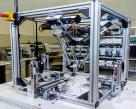 OvGU의 픽 앤 플레이스 데모
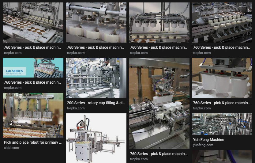 google에서 OvGU Pick and Place demonstrator 검색 결과
3개의 처리 스테이션과 델타 로봇용 PLC 및 처리 스테이션으로 구성됨
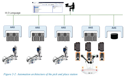 픽 앤 플레이스 스테이션의 자동화 아키텍처
델타 로봇은 각각의 모터 컨트롤러와 함께 3개의 모터를 포함함.
 : 이 문서에서 자체 자산 관리 셸과 함께 제공될 자산 선택
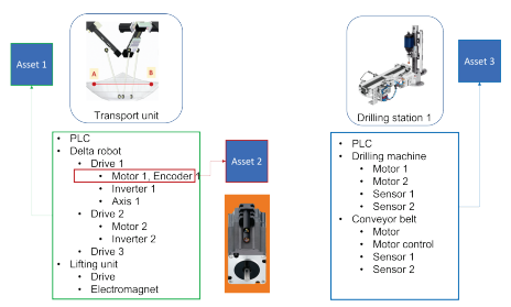
모델링을 위해 다음 자산이 선택됨
- Asset 1 : 전체 운송 장치
- Asset 2 : 델타 로봇의 인코더가 있는 모터
- Asset 3 : 전체 워크스테이션
- Asset 4 : 전체 p&p 스테이션
3 모델링 방법
이 장에서는 예시적으로 선택된 시연자의 자산에 대한 AAS의 모델링 및 생성을 위한 일반적인 절차에 대한 사양이 만들어집니다. 이것은 AAS의 모델링 가능성을 예시적으로 적용한 것임을 다시 한 번 지적해야 합니다. 규범적 주장은 없습니다. 그럼에도 불구하고 의도는 좋은 실용적인 예제 솔루션을 제공하는 것입니다.
3.1 AAS 상호 작용 파트너 역할 설명
AAS는 전체 수명 주기 동안 자산에 대한 정보를 제공하기 위한 것입니다.
AAS의 서로 다른 상호 작용 파트너는 자산에 대해 서로 다른 견해를 갖고 AAS에서 자산에 대해 서로 다른 표현을 기대합니다. 이에 따라 다른 기능과 하위 모델이 관련될 수 있습니다.
AAS 메타모델의 표현 기능의 다양성과 강점을 반영하기 위해 이 장에서는 AAS 상호 작용 파트너의 세 가지 역할을 소개합니다.
첫째, 각 자산이 사용될 플랜트를 계획하고 시운전하기 위한 도구가 가능한 상호 작용 파트너로 간주됩니다.
서비스 요청자와 서비스 제공자는 세 번째 상호 작용 파트너 역할로 도입되었습니다.
P&P 스테이션의 일부 구성 요소는 특정 I4.0 애플리케이션 시나리오에서 자율 서비스 제공자로 간주될 수 있기 때문에 운송 장치 및 워크스테이션과 같은 운송 또는 드릴링 서비스 제공자입니다.
이러한 AAS 상호 작용 파트너 역할을 특성화하기 위해 이러한 역할의 관점에서 AAS 콘텐츠에 대한 최종 요구 사항이 지정됩니다.
AAS 상호 작용 파트너 역할의 정의, 하위 모델 선택 및 해당 내용은 보편적인 성격이 아니며 이 문서의 컨텍스트에서만 적용됩니다.
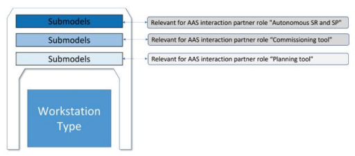 그림 3-1: AAS 상호 작용 파트너 역할
3.1.1 AAS 상호 작용 파트너 역할 “공장 계획 도구”
복잡한 플랜트의 계획은 플랜트의 수명 단계에서 중요한 역할을 합니다.
플랜트 계획자 또는 플랜트 설계자는 계획된 플랜트의 속성에 대한 기본 요구 사항이 정의된 사양 시트를 만듭니다.
구성 요소 제조업체는 구성 요소에 대한 기술 데이터 설명을 작성합니다.
이 설명은 해당 하위 모델과 함께 AAS 형식의 Industry 4.0 개념을 사용하여 제공됩니다.
I4.0의 의미에서 구성요소의 요청된 속성과 보장된 속성의 비교 또는 필수 속성의 이행 검증은 계획 도구의 도움을 받아 가능한 한 자동화 또는 반자동화되어야 합니다.
이를 위해서는 구성 요소의 해당 하위 모델 형태로 자산 유형의 AAS 속성에 대한 일관되고 상호 운용 가능한 설명이 필요합니다.
이 설명은 계획 도구에서 읽고 올바르게 해석해야 합니다(그림 3-2).
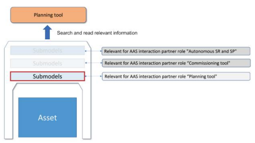 그림 3-2: 플랜트 설계 도구의 하위 모델 선택
- Technical data for the planners of a system (시스템 계획자를 위한 기술 데이터)
- Electrical, pneumatic, hydraulic and mechanical interfaces (전기, 공압, 유압 및 기계 인터페이스)
- Operating conditions (e.g. climatic, operating temperatures) (작동 조건(예: climatic, 작동 온도)
- Functional inputs and outputs (기능 입력 및 출력)
- Assembly instructions (조립 지침)
- Assembly instructions (유지보수 관리)
3.1.1 AAS 상호 작용 파트너 역할 “Commissioning Tool”(시운전 도구)
AAS는 또한 자산과 테스트 및 시운전을 위한 엔지니어링 및 제어 소프트웨어의 결합을 허용하는 자산의 기술 중립적 상호 운용 가능한 인터페이스를 제공할 수 있습니다. 자산 인터페이스로서의 AAS는 시운전 엔지니어가 자산을 매개변수화하고 자산의 기능 테스트를 수행할 수 있도록 해야 합니다. 이를 위해 자산의 기능을 호출하고 제어할 수 있어야 합니다(그림 3-3). 플랜트에 필요한 프로세스 기능을 입증하려면 시운전 엔지니어가 자산 기능을 확인하고 관련 센서 데이터를 읽을 수 있어야 합니다. 이 데이터는 예를 들어 플랜트 기능에 대한 추가 정보를 제공하는 특성 곡선을 생성하는 데 사용할 수 있습니다.
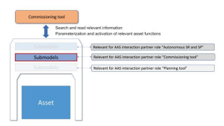 시운전 도구의 하위 모델 선택
- Nameplate (명판)
- Documentations (문서)
- Technical data for commissioning engineers (시운전 엔지니어를 위한 기술 데이터)
- Measuring and control ranges (측정 및 제어 범위)
- Electrical and communication interfaces (전기 및 통신)
- Submodels for functional data (기능 데이터의 submodel)
- Actual data of measured and control values, e.g. “motor current”, “position” (측정 및 제어 값 : 예: “모터 전류”, “위치”)
- Setting parameters of the devices and components (장치 및 구성 요소의 매개변수 설정)
- Status and diagnostic values about the plant and about the devices and components (o 설비 및 장치 및 구성 요소에 대한 상태 및 진단 값)
3.1.3 AAS 상호 작용 파트너 역할 “서비스 요청자 및 서비스 제공자”
계획자 및 시운전 엔지니어를 위해 하위 모델에서 제공하는 자산의 속성 및 기능에 대한 의미상 모호하지 않은 기계 판독 가능 설명은 자동화 기술 구성 요소의 상호 운용성과 통합을 높이는 중요한 단계입니다.
적용 영역은 자산의 실제 생산 능력을 자신의 생산 및 작업 계획에 포함시키려는 운영자의 생산 현장이며 따라서 ERP 또는 MES 시스템과의 쉬운 통합을 목표로 합니다.
그러나 특정 I4.0 애플리케이션 시나리오에는 프로덕션의 특정 자율성이 필요합니다.
시스템 및 해당 구성 요소, 예. 생산 활용의 동적 최적화, 기계 고장으로 인한 가동 중지 시간 방지, 주문 기반 생산, 로트 크기 1에서 비용 최적화 생산을 위한 생산 자원의 동적 오케스트레이션.
이를 위해 AAS의 하위 모델은 자산 기능 또는 자산이 제공하는 서비스에 대한 정보를 상호 작용 파트너에게 제공할 수 있어야 합니다.
이러한 시나리오에서 자산은 자율 서비스 제공자 또는 서비스 요청자가 됩니다(그림 3-4).
AAS를 통해 VDI/VDE 2193 - 입찰 절차 지침에 정의된 것과 같은 수평적 프로토콜 기반 상호 작용에 참여할 수 있습니다.
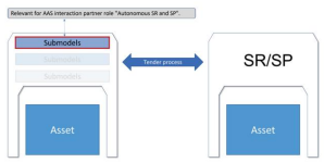 그림 3-4: 자율주행 서브모델 선택 AAS
• 자산의 용도는 무엇입니까?
- as-set의 기능은 무엇입니까?
- aaset/I4.0 구성 요소가 제공할 수 있는 서비스는 무엇입니까?
- 요구 사항의 세부 검증을 위한 기술 데이터(계획서 참조)
3.1.4 모델링을 위한 일반적인 절차에 대한 사양
이 문서에서는 P&P 스테이션(그림 2-2의 기본 구조)이 I40 시스템에서 디지털 방식으로 표현되고 자체 AAS와 통합될 수 있는 방법을 설명합니다.
다음 가정 및 요구 사항은 P&P 스테이션의 AAS 구조를 구축했습니다.
I4.0 구성 요소는 자산과 AAS로 구성됩니다. 자산은 자체 AAS 또는 이 자산이 구성요소인 AAS의 하위 모델로 설명될 수 있습니다. 이것은 SelfManagedEntity 및 CoManagedEntity에 의해 설명됩니다. 이것은 BOM(Bill of Material)에 예시되어 있습니다.- 자체 관리 자산의 일부 AAS에는 BoM(semanticId BoM이 있는 하위 모델)이 있습니다.
- 기계 부품이 있는 프레임워크는 P&P 스테이션 AAS의 하위 모델로 설명되며 자체 AAS가 없습니다.
- 본 문서에 사용된 구성요소는 P&P 스테이션의 구성요소 또는 일반적으로 자산의 구성요소입니다.
- 자산은 독립 구성 요소로 간주되는 하나 이상의 AAS와 함께 제공됩니다. 이것의 이면에 있는 아이디어는 독립 실행형 구성 요소 자체에도 일관된 설명이 포함되어 있다는 것입니다. 공급자가 제공합니다. 이러한 자산을 “Self-ManagedEntity”(5.5)라고 합니다.
- 전체 P&P 스테이션은 자산으로 간주되며 자체 AAS를 받습니다. P&P 스테이션의 AAS에는 특수 하위 모델의 소위 복합 구성 요소로 다른 모델링된 자산의 AAS에 대한 참조가 포함되어 있습니다.
- 자산은 실제로 P&P 스테이션에 내장된 자동화 구성 요소로 이해됩니다. 따라서 이러한 자산의 AAS는 자산 인스턴스의 AAS로 이해됩니다.
- 또한 자산 유형이 존재한다고 가정합니다. 완전성을 위해 자산 인스턴스의 AAS 외에도 해당 자산 유형의 선택된 AAS가 이 문서에서 모델링됩니다. AAS는 자산의 디지털 표현입니다. 다양한 라이프 사이클 단계에서 이 디지털 표현은 다양한 상호 작용 파트너에서 사용됩니다.
- 다양한 상호 작용 파트너가 자신과 관련된 하위 모델을 식별할 수 있도록 AAS 콘텐츠를 구성하기 위한 “보기” 개념이 예로 도입되었습니다. 보기를 사용하여 자산 유형 및 자산 인스턴스와 관련된 정보를 그룹화할 수도 있습니다. 그러면 두 측면 모두 AAS 내에 포함될 수 있습니다.
- 각 AAS에는 Nameplate, Documentation 및 TechnicalData에 대한 하위 모델이 있습니다.
그림 3-5는 AAS에서 P&P 스테이션의 선택된 구성 요소의 가능한 매핑의 일부를 보여줍니다. 원칙적으로 자산 유형과 자산 인스턴스는 구별됩니다. 자산 유형은 카탈로그 데이터 및 기타 계획 문서에 의해 설명되며 아직 개별 장치 또는 구성 요소에 대한 특정 정보(예: 가능한 전압 공급 장치 변형)가 없습니다.
그림 3-5는 델타 로봇(DeltaRobot), 워크스테이션 및 모터로 구성된 P&P 스테이션(PandPtype)만 발췌한 것입니다. 각 자산 유형은 예를 들어 판매와 함께 제공되는 AAS(PaP: AAS)로 표시됩니다. 고려되는 자산 유형에는 P&P 스테이션 자체(PaP1: PandPtype), 델타 로봇(Robot1: DeltaRobot), 워크스테이션(Workstation1: Workstation, …) 및 모터(Motor1: Motor, …)가 포함됩니다. 자산 인스턴스와 자산 인스턴스의 AAS 및 자산 유형의 AAS 사이에는 5.6장에서 더 자세히 설명된 관계가 있습니다. 이들은 여기에서 링크(자산 인스턴스와 AAS 간 - 실선) 및 종속성(자산 유형과 AAS 간 - 실선)으로 설명됩니다.
.png) 그림 3-5 P&P 스테이션의 AAS 모델링 개요(세부 사항)
그림 3-5 P&P 스테이션의 AAS 모델링 개요(세부 사항)
그림 3-6 ~ 3-8은 이 문서에 설명된 AAS의 선택을 예로 보여줍니다.
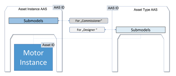 그림 3-6: AAS 내에서 모터를 나타내기 위해 4장에서 생성된 하위 모델
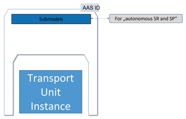 그림 3-7: 운송 장치 매핑을 위해 4장에서 만든 하위 모델
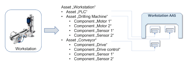 그림 3-8: 워크스테이션 매핑을 위해 4장에서 만든 하위 모델
복합 자산의 모델링을 위해 여기에서 두 가지 다른 접근 방식이 사용됩니다. 이것은 디자인의 범위를 설명하기 위한 것입니다.
그림 3-9는 모터(여기서는 인코더)의 개별 구성요소에 대한 추가 정보가 조립된 자산의 하위 모델에서 설명될 수 있는 방법을 보여줍니다. 이는 개별 부품이 서로 영구적으로 연결되어 있고 자산(여기서는 모터)이 일반적으로 조립식으로만 구매되는 경우 의미가 있습니다. 이 모델링 접근 방식을 통해 모터 제조업체는 AAS를 다음 가치 창출 파트너에게 전달하지 않고도 인코더에 대한 정보(예: 위치 정확도)를 포함할 수 있습니다. 다른 하위 구성 요소는 별도의 하위 모델에 설명되어 있습니다. 이는 구성 요소가 전체로서만 획득될 수 있는 경우에 의미가 있습니다. 설명은 4.3장과 4.4장에서 찾을 수 있습니다.
그림 3-10은 다른 접근 방식을 보여줍니다. 여기에서 하위 구성 요소에는 자체 AAS가 장착되어 있습니다. 이는 하위 구성요소를 별도로 구매하여 사용자 사이트에서 조립하는 경우 의미가 있습니다. 설명은 4.6장과 4.7장에서 찾을 수 있습니다.
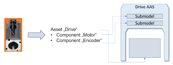 Figure 3-8 The submodels created in chapter 4 for mapping the workstation
 Figure 3-10 AAS of the workstation refers to the AAS of Built-in Assets of the workstation
3.2 설명을 위한 AASX 패키지 탐색기 사용
제시된 모델링은 일반적으로 모델링 요소와 가능성을 설명하는 예로 이해해야 합니다. 그것들은 사양이 아닙니다. 따라서 다른 예에서 다른 모델링 옵션이 사용되는 경우가 있습니다.
설명을 위해 모든 예제는 현재 사용 가능한 버전의 AASX 패키지 탐색기로 작성되었습니다. AASX 파일은 http://liabroker.ddns.net:51001/에서 볼 수 있습니다.
패키지 탐색기의 모든 예시적인 구현이 현재 AAS 사양의 버전 3.0 RC01을 준수하는 것은 아닙니다. 그럼에도 불구하고 저자는 AASX 모델과 결과 스크린샷이 이해를 지원한다고 믿습니다.
4 P&P 스테이션의 선택된 구성 요소 모델링
이 장에서는 AAS 및 하위 모델의 형태로 2장에서 선택한 자산의 예시적인 모델링을 설명합니다. 제시된 모델링은 3장에서 설명한 모델링 방법을 기반으로 합니다.
4.1 계획의 관점에서 본 P&P 스테이션
시연자는 3개의 워크스테이션이 서로 다른 기능을 제공하는 P&P 스테이션입니다.
델타 로봇은 워크스테이션 간의 운송 작업을 처리합니다. 플래너는 먼저 대략적인 시각을 갖고 델타 로봇과 워크스테이션을 별도의 구성 요소로 간주합니다.
이와 관련하여 P&P 스테이션은 I4.0 복합 구성 요소입니다(그림 4-1). 재료 명세서(BoM)에는 모든 구성 요소가 나열됩니다.
이에 대해서는 5.6장에서 자세히 설명합니다. 이 모델링(3.2장)에 대해 지정된 대로 P&P 스테이션의 AAS에는 Nameplate, Documentation 및 TechnicalData 하위 모델이 있습니다. 명판 및 문서 하위 모델은 해당 하위 모델 템플릿을 기반으로 합니다.
자세한 내용은 [DNI20] 및 [DD20]에서 확인할 수 있습니다. 이러한 하위 모델에서 스테이션은 전기 연결 값 및 기하학적 치수와 같이 전체적으로 설명됩니다.
그러나 계획자는 구성 요소의 기술적 세부 사항도 필요합니다.
따라서 P&P 스테이션의 AAS는 구성 요소의 AAS와 관계가 있습니다.
이들은 별도의 하위 모델 CompositeRelationship에 저장됩니다(자세한 설명은 5.8장 참조).
P&P 스테이션 AAS의 진입점을 통해 스테이션에 속한 모든 구성 요소와 해당 데이터를 찾을 수 있습니다. 여기에는 구성 요소의 유형 관련 데이터가 포함됩니다.
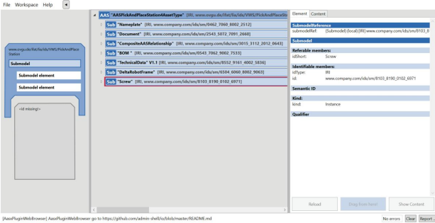 그림 4-1: 하위 모델 개요 P&P 스테이션 유형
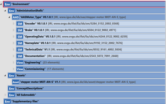 그림 4-2: 모터 유형의 AAS 보기
4.2 시운전 관점에서 본 P&P 스테이션
설계 작업이 완료되고 구성 요소가 주문 및 배송되면 조립 및 시운전을 수행해야 합니다.
P&P 스테이션 인스턴스의 AAS는 이 예에서 3개의 워크스테이션과 1개의 델타 로봇에 있는 모든 인스턴스 관련 AAS를 나타냅니다.
다음 장에서 설명하는 것처럼 I4.0 구성 요소의 하위 모델 항목은 자산 유형과 자산 인스턴스를 설명하는 항목이 다릅니다.
P&P 스테이션 인스턴스의 AAS는 P&P 스테이션 유형의 AAS의 AASId가 입력되는 AAS 속성 derivedFrom을 사용합니다.
derivedFrom은 고전적인 객체 지향 유형/인스턴스 관계를 설명하지 않습니다.
여기에서는 자산 인스턴스 AAS가 인스턴스화 중에 자산 유형 AAS의 요소를 한 번 인수하거나 다른 AAS의 데이터를 참조하여 액세스할 수 있게 한다고만 표시됩니다. 이 과정에서 AAS의 요소는 변경, 단축 또는 보완될 수 있습니다.
4.3 계획 및 시운전의 관점에서 본 모터 유형
데모에는 Delta 로봇을 제어하기 위한 3개의 스테퍼 모터가 포함되어 있습니다.
3개의 모터는 모두 동일한 제품 유형의 표현입니다. 따라서 AAS는 이 유형에 대해 모델링됩니다.
그림 4-2는 AASX 패키지 탐색기에서 모터 유형의 AAS 표현을 보여줍니다.
자산 및 관련 AAS가 생성됩니다. 자산은 모터 유형을 나타내므로 AssetKind 유형입니다.
AAS에는 6개의 하위 모델이 포함되어 있으며 선택은 모터 문서 [IGUS03]의 구조를 기반으로 합니다. 하위 모델의 모든 ID 앞에는 www.ovgu.de 도메인이 옵니다.
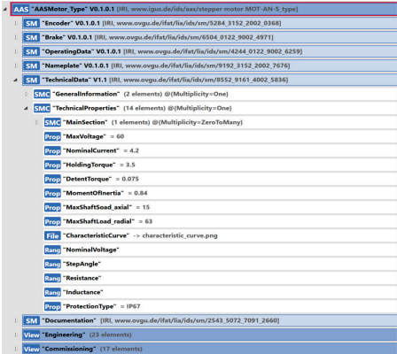 그림 4-3: SubmodelElement 유형이 다른 하위 모델 TechnicalData
여기에 있는 모든 하위 모델은 ModelingKind 인스턴스에서 가져온 것입니다. submodeElements는 하위 모델 모델링 종류에서 해당 종류를 상속합니다. 종류 템플릿의 하위 모델에 있는 하위 모델 요소도 종류 템플릿에서 가져옵니다. 모든 SubmodelElement는 ECLASS 또는 IEC61360-CDD와 같은 표준에 대한 IRDI 또는 IRI 유형의 GlobalReference를 참조하는 semanticId를 전달합니다.
그림 4-3은 SubmodelElements의 다른 하위 유형이 사용되는 TechnicalData 하위 모델의 예를 보여줍니다.
자주 사용되는 속성 유형 외에도 이 하위 모델에는 속성의 값 속성에 범위를 할당하거나 파일을 참조하기 위해 유형 범위 및 파일도 포함됩니다.
식별자 보호 유형이 있는 속성은 ValueID를 사용하여 ValueList의 표준화된 값(예: IP65, IP67)도 참조합니다.
개별 하위 모델 요소는 엔지니어링 또는 시운전 두 가지 보기 중 하나에 할당됩니다. 따라서 다른 사용자 역할은 관련성이 있다고 생각하는 하위 모델 요소에 구체적으로 액세스할 수 있습니다.
4.4 계획 및 시운전의 관점에서 본 모터 인스턴스
그림 4-4는 AASX 패키지 탐색기에서 모터 인스턴스의 AAS 보기를 보여줍니다.
이렇게 총 3가지가 있습니다. 자산 및 관련 AAS가 생성되었습니다.
자산은 모터의 인스턴스를 나타내므로 ModelingKind 인스턴스에서 가져옵니다.
하위 모델 명판과 관련하여 모델링 종류 템플릿이 이제 필요하지 않기 때문에 AAS에는 이제 5개의 하위 모델만 포함됩니다.
대신 Nameplate의 모든 하위 모델 요소는 이제 구체적인 값을 가지므로 Modeling-Kind Instance의 단일 하위 모델로 결합됩니다.
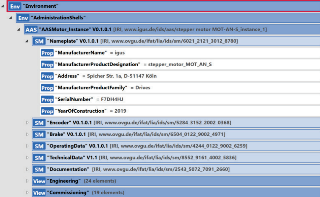 Figure 4-4: 모터 인스턴스의 AAS 보기
인스턴스 AAS에는 엔지니어링 및 시운전이라는 두 가지 보기도 포함되어 있습니다. 그림 4-5는 시운전 보기의 예를 보여줍니다.
다양한 하위 모델의 하위 모델 요소에 대한 참조를 볼 수 있습니다. 보기에 대한 할당은 예시로 간주되며 자산 및 해당 AAS의 의도된 사용에 따라 달라집니다.
메타모델 자체는 이에 대한 기준을 제공할 수 없습니다. 다른 측면에서 인스턴스 AAS는 위에서 설명한 유형 AAS와 다르지 않습니다.
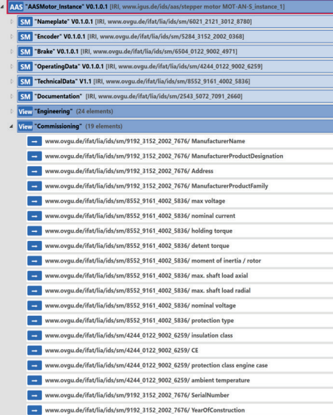 Figure 4-5: “Commissioning” 보기가 확장된 모터 인스턴스의 AAS 보기
4.5 운송 장치의 AAS: SP/SR용 하위 모델
이전 장에서는 자산의 기능, 매개변수 및 상태를 속성을 하위 모델로 사용하여 모델링하는 방법에 대해 설명했습니다.
다음 과제는 자산의 용도를 정확하게 정의할 수 있도록 자산이 적합한 대상을 설명하는 것입니다.
자산을 CPS에 통합하려면 이 개체가 해당 AAS의 기능에 대한 관련 정보와 설명을 제공해야 합니다.
I4.0 시스템에서 일부 I4.0 구성 요소는 계약 협상을 지원하여 프로덕션 서비스를 가져올 수 있습니다.
Industrie 4.0에 적용된 서비스 시스템에서 일부 I4.0 구성 요소는 서비스 제공자 또는 사용자로 이해될 수 있습니다.
사용 가능한 서비스 및 제공된 기능에 대한 정보는 모든 상호 작용 파트너가 동일한 방식으로 이해할 수 있도록 제공되어야 합니다.
I4.0 커뮤니티의 오늘 토론에서 function, functionality, capability, skill, operation, process and service 라는 용어는 자산의 효과를 설명하는 데 중심 역할을 합니다.
그러나 저자는 이러한 용어의 명확한 정의에 대한 개념을 알지 못합니다.
이 문서에서 function, functionality, capability 이라는 용어는 동의어로 간주되며 AAS 메타모델 요소인 capability(기능) 으로 모델링됩니다.
service 라는 용어는 고객에게 특정 제안을 제공하는 기능과 이러한 제안에 대한 액세스 모두에 사용됩니다.
예를 들어 서비스가 속성으로 모델링되는 경우 기능 하위 모델 요소를 이 용도로 사용할 수 있습니다.
속성은 기능 하위 모델 요소가 입력된 하위 모델에 있거나 속성이 하위 모델에서 참조에 의해 하위 모델에서 기능 하위 모델 요소로 연결된 다른 하위 모델에 있을 수 있습니다.
기능 하위 모델 요소는 자산 또는 구성 요소가 특정 기능을 수행하는 기능을 설명합니다. 다양한 기능 하위 모델 요소를 설명하기 위한 기능 세트는 기능에 따라 다르며 제품 설명 표준(예: ECLASS)의 각 기술 기능에 대해 제공될 수 있습니다.
그림 4-6과 같이 이 장에서 고려하는 자산은 운송단위이다. 이 자산의 작업 또는 예상되는 효과는 P&P 스테이션 내에서 A에서 B로 공작물을 운송하는 것입니다.
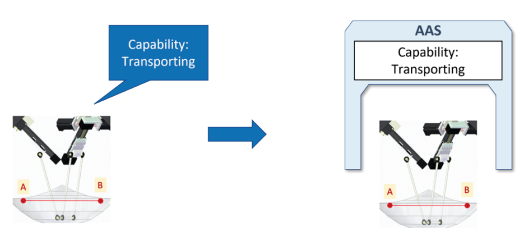 시스템의 전송 장치가 자율 서비스 제공자 역할을 하는 경우 해당 기능과 제공 서비스는 AAS에 설명되어 있습니다.
따라서 A(시작 위치)에서 B(목적지 위치)로 물건을 운송하는 운송 장치의 능력은 능력 개념[PLA20]으로 모델링됩니다.
그림 4-7은 예시적인 모델링 접근 방식을 보여줍니다. 이 예에서 Capability(기능) 하위 모델에는 자산에 있는 모든 기능이 포함됩니다.
이 경우 문제의 기능은 Transport(수송)입니다. 기능 Transport(전송)의 SemanticId는 ECLASS 표준의 해당 의미 설명을 나타냅니다.
I4.0 플랫폼[DCI20]의 관련 백서에 설명된 기능 모델링 개념은 자산 기능 설명에 대한 속성을 포함하는 두 번째 하위 모델의 기반을 설정합니다.
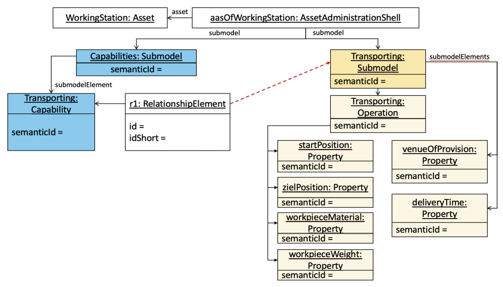 공통 백서 Platform Industrie 4.0 및 BaSys 4.2 프로젝트[DCI20]의 기능 설명 개념을 기반으로 한 “전송” 기능 설명.
모델링 개념은 기능 실행을 용이하게 하기 위해 개별 작업에 대한 일부 기능의 구조화를 제공합니다.
이 예에서 여기에는 시작 및 목표 위치, 운반 작업물의 재료 및 무게가 포함됩니다.
서비스를 모델링하는 경우 기능 설명(기술적) 특성(예: 서비스 제공의 가격, 장소 및 시간) 외에 서비스 설명(상업적) 특성이 하위 모델에 추가될 수 있습니다.
기능 백서[DCI20]에 제시된 AAS 기능 및 AAS 작동의 개념도 다르게 해석될 수 있으므로 기능 설명의 대안적인 단순화된 변형을 상상할 수 있습니다.
그림 4-8에 표시된 기능 설명은 모델링에서 작업을 사용할 필요가 없습니다. 이전 예에서 작업에 할당된 속성은 대체 제안의 Transporting(전송) 하위 모델에 직접 할당됩니다.
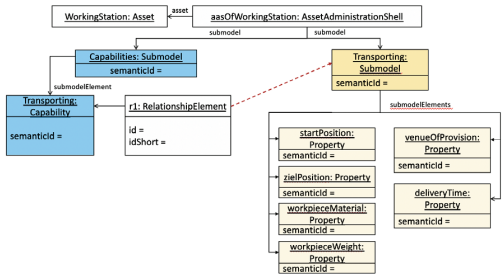 Figure 4-8: “Transport”(전송) 기능을 설명하는 다른 방법
4.6 계획 관점에서 본 워크스테이션 유형
AAS 개념은 I4.0 구성 요소를 새로운 상위 수준 I4.0 구성 요소로 통합하는 것을 지원합니다[PLA17]. 결과적으로 처리 스테이션(워크스테이션)의 자산 및 AAS 구조를 모델링하는 다양한 방법이 있습니다.
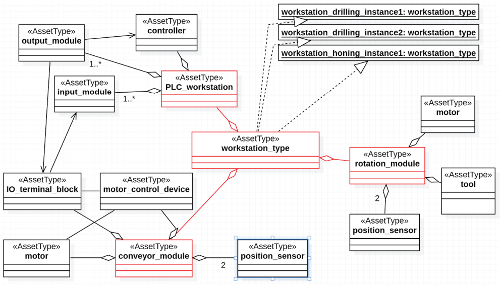 Figure 4-9 - 워크스테이션 클래스 다이어그램
이 섹션에서 워크스테이션을 구성하는 구성 요소는 각각 별도의 AAS로 개별적으로 모델링됩니다(그림 4-9 참조).
그러면 워크스테이션은 컨트롤러, 컨베이어 벨트 및 드릴링 모듈과 같은 다양한 하위 자산으로 구성된 자산입니다.
이는 워크스테이션이 여러 공급업체 구성 요소 집합으로 구성되어 있기 때문에 실제로 생각할 수 있습니다. 가능한 미래 시나리오에서 해당 구성 요소의 AAS는 공급자가 제공하고 제조업체(또는 시스템 통합자)(이 경우 OvGU)가 워크스테이션의 AAS에 통합할 수 있습니다.
AssetType workstation_type의 세 가지 인스턴스가 P&P 스테이션에 내장되어 있습니다. RAMI 4.0에 따르면 자산의 제품 수명 주기를 유형 및 인스턴스 정보에 따라 구분하는 것이 합리적입니다(섹션 5.6 참조). 이 섹션에서는 워크스테이션에 대한 AAS 모델링을 AssetType으로 보여줍니다. AssetType의 AAS에서 AssetInstance의 AAS를 파생하는 방법에 대한 제안은 섹션 4.6에 설명되어 있습니다.
PLC(PLC_workstation) 외에, workstation_type은 컨베이어(conveyor_module)와 회전 모듈(rotation_module)로 더 구성됩니다. 또한 이러한 자산은 액추에이터 및 센서와 같은 다른 하위 자산으로 구성됩니다. 관련된 노력으로 인해 첫 번째 수준의 하위 자산만 모델링됩니다(그림 4-9에서 빨간색으로 표시된 클래스 및 집계 관계 참조).
이 I4.0 구성 요소에 대한 관계는 별도의 하위 모델에 할당됩니다. 이 하위 모델에는 구현된 예(그림 4-10에서 빨간색으로 표시)에서 함께 속한 자산 간의 관계가 포함되어 있습니다. 관계는 AAS 수준이 아니라 자산 수준(그림 4-10 참조)에서 입력됩니다. 그 이유는 자산은 원칙적으로 여러 AAS를 가질 수 있고 교환이 더 많은 노력으로 이어질 수 있기 때문입니다. 아마도 자산 교환은 덜 빈번합니다. 이 작업을 위해 특별히 의도된 또 다른 변형은 BOM(BoM, 5.5장)이 사용되는 복합 구성요소(5.7장 참조)로 모델링하는 것입니다.
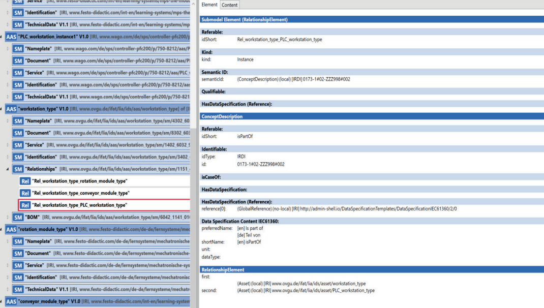 Figure 4-10 - 하위 모델 “Relationships”(관계)에서 AAS 워크스테이션의 하위 자산 간의 관계 정의
각 AAS는 하위 모델 명판, 문서(관련 문서 모음), 서비스(지원/유지 관리에 관한 정보), 식별(식별 속성) 및 TechnicalData(기술 속성)로 구성됩니다.
속성 선택 및 값 할당은 제조업체에서 제공하는 정보를 기반으로 합니다. 이것은 이 문서의 작성자에 의해 결정되거나 자산의 명판에서 읽습니다(표 4-1 참조). PLC_workstation_type 제어의 AssetType에 특별한 경우가 고려됩니다. 여기에서 유형 정보는 특정 제조업체에서 가져온 것이 아닙니다. 고려한 시나리오에서 워크스테이션의 시스템 통합자는 재고에 따라 다양한 유형의 PLC를 설치하기로 결정했습니다. 원칙적으로 이러한 제품은 다른 제조업체에서도 제공될 수 있습니다. 그러나 시스템 통합자는 TechnicalData 하위 모델에서 언급된 특성이 가정됨을 보장합니다.
일부 하위 모델 요소가 동일하기 때문에 명판과 식별의 공동 사용은 중복되어 보입니다. 이것은 다양한 사용 사례에서 사용하기 때문입니다. 불일치로 이어질 수 있는 오류의 한 가지 원인은 동일한 이름을 가진 하위 모델 요소에 다른 값을 할당하는 것입니다.
특히 TechnicalData 하위 모델은 계획된 시설의 요구 사항을 충족하는 구성 요소를 찾고 있는 계획자에게 흥미로운 것으로 보입니다. 이러한 의미에서 여기에서 이 하위 모델의 기능은 해당 자산 유형이 이러한 기능을 충족할 것이라는 보장을 나타냅니다.
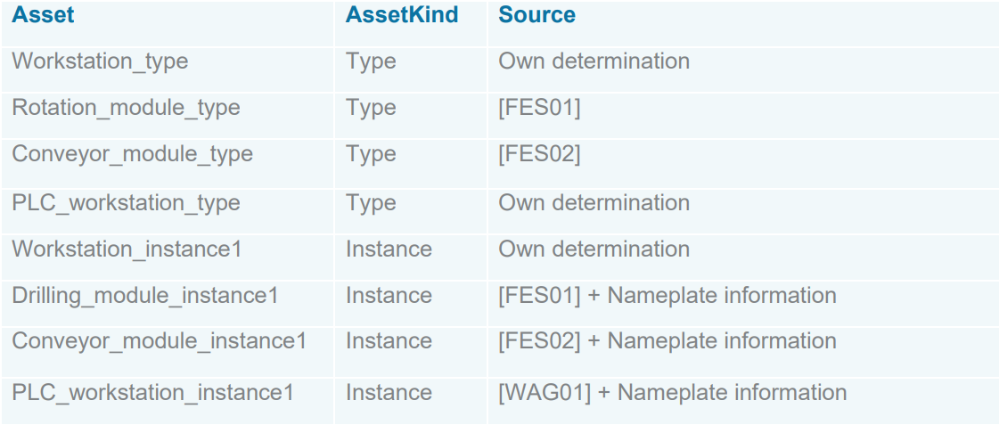 Table 4-1 - 워크스테이션의 하위 모델에 대한 정보 소스
4.7 계획 관점에서 본 워크스테이션 인스턴스
다음은 워크스테이션의 AssetInstance의 AAS가 어떻게 모델링되었는지 보여줍니다.
종류 인스턴스의 자산은 한 번만 존재하는 구체적인 자산입니다. P&P 데모에는 workstation_type 유형의 세 가지 인스턴스가 있습니다.
단, 예시로 드릴링_워크스테이션_인스턴스 인스턴스만 모델링하였습니다.
instantiation(인스턴스화)는 기존 AAS workstation_type을 재귀적으로 복사하여 AASX 패키지 탐색기에서 수행되었습니다.
이 컨텍스트에서 재귀는 모든 하위 모델과 해당 내용이 소스 AAS에서 인계됨을 의미합니다.
새 AAS의 idShort 및 id, 해당 하위 모델 및 자산의 이름을 바꿔야 합니다.
AssetType의 AAS에서 파생된 것은 DerivedFrom 참조로 표시될 수 있습니다(그림 4-11 참조).
AssetType의 AAS에서 AAS를 파생할 때 SubmodelElements와 관련하여 다양한 결과가 발생할 수 있습니다
- SubmodelElement의 유형은 변경될 수 있습니다.
- Example: 워크스테이션_유형의 컨베이어 벨트 길이는 주문 시 고객이 특정 제한 내에서 구성할 수 있으므로 범위로 모델링됩니다. 마지막으로 인스턴스의 컨베이어 벨트는 길이가 고정되어 속성이 됩니다.
- 속성의 의미가 변경되고 다른 semanticId를 받을 수 있습니다.
- Example: 플래너는 PLC 유형에 최소 8개의 디지털 입력이 필요하다고 지정합니다(MinNumberOfIn-puts: 0173-1#02-AAP328#001). PLC의 인스턴스에는 8개의 입력이 있습니다(NumberOfInputs: 0173-1#02-AAP508#003).
각 AssetKind의 설명과 관련된 속성만 AAS에서 모델링됩니다. 인스턴스 수준에 존재하지만 AssetType의 설명과 관련이 없는 특성은 AssetInstance의 AAS에 있는 적절한 하위 모델에 추가되어야 합니다. 예를 들어 자산의 일련 번호가 있습니다. 이 기능은 AssetInstance의 AAS에서만 모델링됩니다.
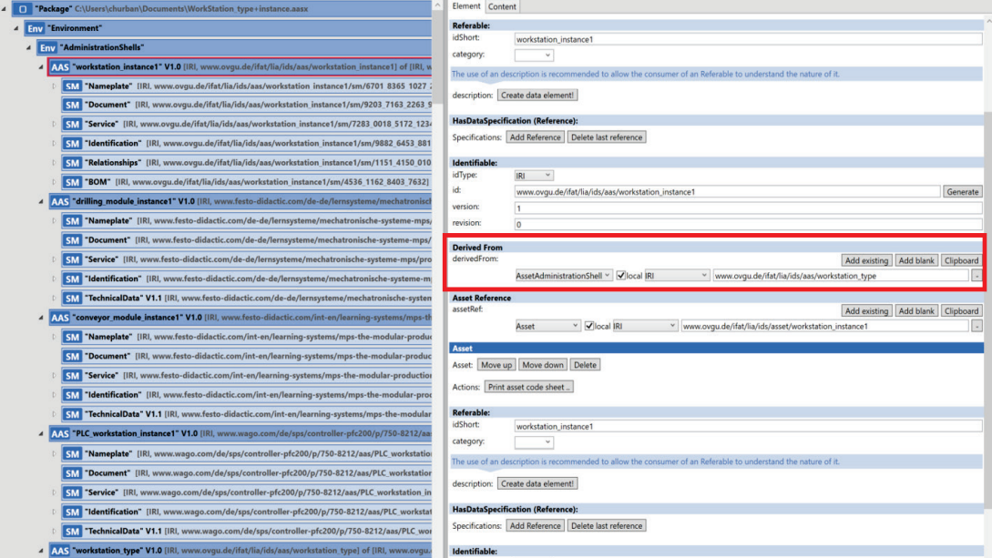 Figure 4-11: 파생 - 자산 종류:유형 AAS-에서 AAS 파생
4.8 워크스테이션 인스턴스: SP/SR를 위한 Submodel
기능 하위 모델 요소가 있는 자산의 기능 및 서비스를 모델링하는 개념은 4.6장에서 소개됩니다. 반복을 피하기 위해 일반적인 설명은 관련 장을 참조하십시오.
이 장에서는 워크스테이션의 drilling(드릴링) 기능에 대한 예시적인 모델링을 참조합니다.
기능 백서[DCI20]의 예를 기반으로 하는 워크스테이션 기능(이 경우 drilling(드릴링))에 대한 추상적인 설명이 그림 4-12 및 그림 4-13에 나와 있습니다.
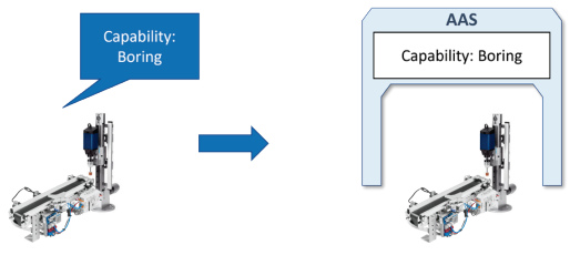 Figure 4-12: I4.0 시스템의 워크스테이션이 자율 서비스 제공자 역할을 하는 경우 해당 기능과 제공 서비스는 AAS에 설명되어 있습니다.
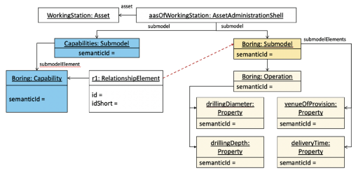 Platform Industrie 4.0 및 BaSys 4.2 프로젝트[DCI20]의 기능 백서를 기반으로 하는 “드릴링” 기능에 대한 설명.
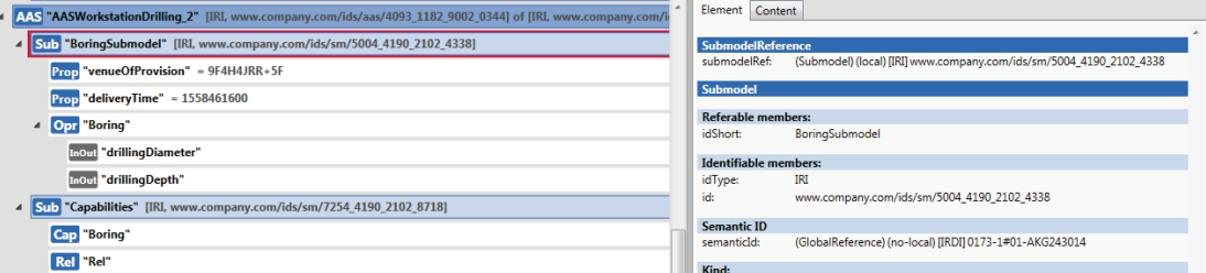 Figure 4-14: AASX 패키지 탐색기에서 “드릴링” 기능에 대한 설명 구현
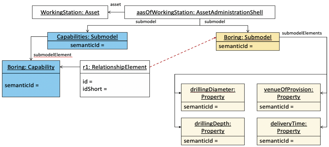 Figure 4-15: “드릴링” 기능 설명에 대한 대안 제안
그림 4-14는 Drilling(드릴링) 기능에 대한 설명이 AASX 패키지 탐색기에서 구현되는 방법을 보여줍니다.
AAS 능력과 AAS 운영 개념은 또한 다르게 해석될 수 있으므로 능력 설명의 대안적 변형을 상상할 수 있습니다.
그림 4-15에 표시된 기능 설명에서는 작업을 사용할 필요가 없습니다.
이전 예에서 작업에 할당된 속성은 대체 제안의 Boring(지루한) 하위 모델에 직접 할당됩니다.
그림 4-16은 AASX 패키지 탐색기에서 작업을 사용하지 않고 Drilling(드릴링) 기능에 대한 설명을 구현하는 방법을 보여줍니다.
 in the AASX Package Explorer.png) Figure 4-16: AASX 패키지 탐색기에서 기능 설명(옵션 2) 구현
Figure 4-16: AASX 패키지 탐색기에서 기능 설명(옵션 2) 구현
5 AAS 모델링 개념
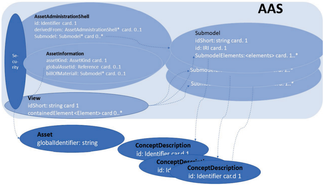 Figure 5-1: AAS의 기본 구조 개요
이 장에서는 AAS 모델링의 필수 개념을 강조하고 이를 예로 제시합니다. 목표는 구체적인 작업에 대한 서로 다른 모델 요소의 상호 작용을 설명하는 것입니다.
5장의 예는 델타 로봇을 참조합니다. 따라서 기술 문서[IGUS01]는 자산 관련 정보 소스로 전체적으로 사용됩니다.
5.1 AAS의 기본 구조 및 선택된 중요 속성
이 장에서는 AAS의 대략적인 구조를 설명하고 이를 예로 제시합니다. 목표는 모델링을 위한 진입점을 설명하는 것입니다.
자산 관리 셸(AAS)은 자산 정보의 최상위 수준, 하위 모델 및 보기로 구성됩니다. 이러한 모든 정보 단위에는 더 자세히 설명하는 속성이 있습니다. 카디널리티가 있는 속성 선택이 그림 5-1(흰색 글꼴)에 나와 있습니다. 보안 속성 및 기능은 모든 요소에 일관되게 고정됩니다.
Asset 및 ConceptDescriptions는 AAS 내부에 속하지 않습니다. 자산은 AssetInformation에 의해 설명됩니다. AssetInformation에는 자산에 대한 참조가 포함됩니다. 또한 하위 모델로 설명되는 BoM(Bill of Material)을 참조할 수 있습니다. 일부 SubmodelElement(예: Property)는 semanticId를 사용하여 ConceptDescription(점선)을 참조합니다. ConceptDescription은 추가 설명 정의를 제공합니다(5.3장 참조).
5.2 요소 식별
5.2.1 챕터의 목적
AAS 요소 식별을 위한 개념의 사용 프레젠테이션.
AAS in detail(AAS 세부사항) 사양의 기본 장:
- Chapter 4.4.3 “Identifiers for Assets and Administration”(자산 및 관리에 대한 식별자)
- Chapter 4.4.4. “Which Identifier to use in which Elements”(어떤 요소에 어떤 식별자를 사용할지) (Table 2)
- Chapter 4.7.2.2 “Referable”(참조 가능)
- Chapter 4.7.2.3 “Identifiable” (식별 가능한)
5.2.2 패키지 탐색기에 표시
P&P 스테이션의 AAS의 예를 사용하여 Referable(참조 가능) 및 Identifiable(식별 가능) 속성은 그림 5-2에 나와 있습니다.
idShort는 Referable의 필수 속성입니다.
Identifiable을 사용하면 idType에 IRI, IRDI 또는 사용자 지정으로 지정된 다양한 유형의 식별자를 선택할 수 있습니다.
id는 그에 따라 채워집니다.
또한 이 사양은 버전 및 개정판과 함께 제공됩니다.
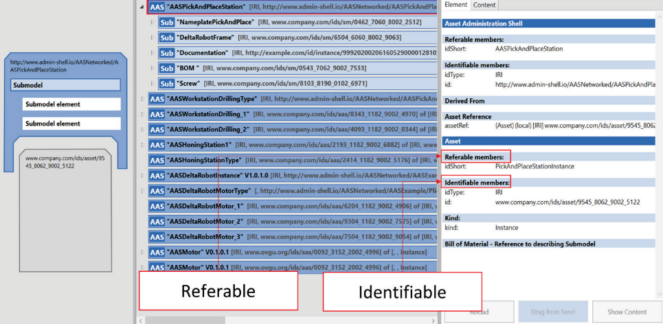 Figure 5-2 - Referable and Identifiable Data for AAS and Asset of the P&P Station
5.2.3 Explanations
Each element of the AAS model needs an identifier in order to be uniquely named in a machine-readable way. This designation is used for the different use cases in which the model elements are required.
A distinction is made between globally unique identification, denoted by “Identifiable” and locally unique identification, denoted by “Referable”. This distinction makes it possible that identifiers can be used identically in several AAS (only possible for idShort). This contributes significantly to the reuse of model parts. Almost all model elements are referable. AAS Identifiable model elements are referable and also have the attributes:
5.3 Semantic assignment to model elements - the “semanticId”
5.3.1 Aim of the chapter
Description of the task of the attribute “semanticId”.
5.3.2 Input information used for the model
Relevant properties, parameters, states of the modelled assets shall be transferred into the characteristics according to IEC 61360. The unique identifiers for features of other model elements are to be taken from the standardised vocabularies. • A vocabulary of semantic definitions favoured by Plattform Industrie 4.0 is the ECLASS standard. • Other vocabularies: Company-specific device classifications and their feature definitions o A user-specific semanticId can be defined in the form of an IRI
PackageExplorer has the option to generate the IRI automatically
5.3.3 Model elements of the AAS metamodel used
- Chapter 4.7.2.7 “Semantic Reference Attributes
5.3.4 Visualization in the Package Explorer
Using the example of “ManufacturerTypeNameAAS” property of the nameplate submodel, a semanticId is shown in Figure 5-
- This shows the reference to the corresponding ConceptDescription, in this case an ECLASS IRDI.
5.3.5 Explanations
In addition to the identification of the model elements, it is intended that each model element has a complementary semantic description. Therefore, the model elements have the attribute “semanticId”.
 Figure 5-3 - SemanticId using the example of a property
[5-3]
Figure 5-3 - SemanticId using the example of a property
[5-3]
This is a reference to the machine-readable description of the model element, i.e. it is a reference to an entry in a dictionary. The preferred case of a dictionary used is one in which the characteristics (property) are described according to the IEC 61360 standard. This standard specifies the attributes to be used for the description.
Almost all model elements (except Asset, ConceptDescription and Asset Administration Shell) have a semantic reference, i.e. the semanticId. The model elements of the AAS also have their own semanticId, which is created in the namespace www.adminshell.io/….
The semanticId is not an identifier that is used for naming and thus for addressing in a use case. The identifiers of Identifiable and Referable are responsible for this. The semanticId is an additional attribute that is available for the content-related technical explanation of the model element. It points to the supplementary description and thus contributes to the assignment of the meaning of the model element. Thus, it clarifies, what is behind the model element. In other words, the attributes of a model element are not stored locally but are defined globally. This means that the same characteristics with the same attributes can be used in different engineering phases. The mapping of feature values during the transition from one technology to another or from one tool to another is no longer necessary.
The AAS metamodel defines entries in a dictionary based on IEC 61360. These entries are referred to as concept descriptions (see 5.8). Only individual entries in a dictionary are referenced by a model element of the AAS. Therefore, there is no dictionary itself in the AAS specification, but only the entries, the ConceptDescriptions.
5.4 Relationship between AAS, Asset and Asset Identification Submodel
[5-4 Reference between AAS and Asset]
5.4.1 Aim of the chapter
- Description of the relationship between asset and AAS in a submodel
- Modelling of the type plate/nameplate of the asset and its referencing in the AAS
5.4.2 Model elements of the AAS metamodel used
- Table P. 58 - attribute “asset” (this is a reference)
- Table P. 59 - attribute “assetIdentificationModel
5.4.3 Explanations and visualization in the Package Explorer
For the representation of the relationships between AAS and asset, the object “AssetInformation” is available from version 3.0 of the AAS specification. Among other things, the asset identification and the asset child are to be specified in this object. The asset identification is specified as globalAssetId, which is to enable a worldwide unique identification. A good possibility is to assign this according to DIN SPEC 91406. Companies usually have their own internal identifiers first, e.g. serial number and order code. These supplementary IDs are to be entered in the externalAssetId, of which there can be several. In addition, a submodel similar to the type nameplate is created in the AAS, which can be uniquely identified by reference from the AssetInformation object. This submodel should be derived from the submodel template “Digital Nameplate” [DNI20]. Typical information for this task is shown in the Figure 5-4.
The asset is not part of the AAS, the I4.0 component consists of asset and AAS. Nevertheless, the asset is modelled in the Package Explorer. The Environment (Env) is responsible for this.
Since the asset information is only available from V3.0 of the AAS specification, it cannot yet be used in the example with the Package Explorer. The corresponding definitions are therefore shown in Figure 5-5 with page reference of the AAS specification in which the definitions are contained.
If assets are composed of several components, their relationships must be described in the Bill of Material (BoM) (see 5.5).
[5-5 - Relationship between AAS, Asset and Asset Identification Submode]
5.5 Bill of material
5.5.1 Goal of this chapter
Representation of the structure of an asset as a submodel “Bill of Material” using the example of DeltaRobot 360.
5.5.2 Model elements of the AAS metamodel used
- Chapter 4.3: Composite I4.0 Components
- Chapter 4.7.5, p. 58 and p. 59: Definition
5.5.3 Explanations and visualization in the Package Explorer
The BillOfMaterial (BoM) is a submodel. It is contained in the AAS of the asset to which the components in the BoM belong. In the AssetInformation is the attribute that contains the reference to the BoM submodel.
If components are included that are composed of further components, this refinement of the corresponding AAS is assigned to the asset consisting of further components.
[5-6: Overview BillOfMaterial P&P Station Instance]
The components of the asset in the BoM are to be modelled as “Entity” in this submodel (Figure 5-6). Relationships between the components (e.g. is part of - isPartOf) are modelled as “RelationshipElement”. The submodel containing the BoM must be provided with the semanticId “http://example.com/id/type/submodel/BoM/1/1” in order to be able to identify this submodel as a BoM.
[5-7: Bill of Material modelling]
The entities correspond in a 1:1 relationship to the assets to be modelled. For the entities, idShort, entityType and the reference (identifiable) to the asset must be specified (Figure 5-7). The attribute “entityType” can be “CoManagedEntity” or “SelfManagedEntity”. CoManagedEntity states that the asset of this entity has no AAS and is managed in the AAS where the BoM is at. SelfManagedEntity states that the associated asset has its own AAS.
[5-8: RelationshipElement example]
The RelationshipElement is used to model the relationships between the entities of the BoM. The relationship is directed and has a starting point (first) and an end point (second). The identification is done by means of idShort and the identifier (IRI) of the corresponding entity (Figure 5-8).
[5-9: isPartOf - Property in the ConceptDescription]
The semanticId of the relationship element contains the meaning of the relationship. In this example, “isPartOf” is identified by “0173-1#02-ZZZ998#002”. There is then an entry for this in the concept description (Figure 5-9).
[5-10: Relationship of the asset to the BoM in the Package Explorer - example]
A special feature of the Package Explorer is that if semanticId = “http://example.com/id/type/submodel/BoM/1/1”, a graphic representation of the BoM appears when the BoM element of the submodel is activated. This appears when the semanticId is entered correctly. In addition, further submodel elements can be specified for an entity to describe the entity, i.e. the asset, in more detail. For example, a reference to the AAS of a self-managed asset or properties for a co-managed asset. This will be explained in more detail. There are components in machines and plants that either do not have their own communication capability (e.g. screws, rods, seals), occur in large quantities or whose individual value (in terms of purchasing costs) is low.
[5-11: Entity overview from the BoM in the Package Explorer]
[5-12: Refined characteristic (property) of the CoManagedEntity screws - here example number of screws]
For these, however, information is still needed to accompany the life cycle. The entityType “CoManagedEntity” applies to these assets. In the example, screws are such “CoManagedEntity” and are modelled accordingly in the BoM (Figure 5-11). The concrete number, for example, should also be modelled and appears as a property of the entity, here in the example “Number of screws” (0173-1#01-RAA001#001), a characteristic that exists in ECLASS (Figure 5-11). The characteristic “Number of screws” is an ECLASS characteristic and is also included in the ConceptDescription (Figure 5-13). Figure 5-12 shows that there can be a submodel in which the screw is described in more detail, here exemplarily only with the property “Execution of the thread”.
[5-13: Entry of the feature “number of screws” in the concept description according to IEC 61360/ECLASS]
This submodel is accommodated in the AAS in which the BoM is located. In addition, this submodel gets a reference to the associated CoManagedEntity. This reference needs a machine-interpretable semanticId to unambiguously express the fact that it is the link between the entity contained in the BoM and its description in a submodel. However, it is also possible that the entity points to the description of entities in a submodel. The comprehensive list of properties of the screws can be found in the enclosed reference.
Figure 5-13 shows a section of the concept descriptions that are modelled in the P&P station.
5.6 The kind attribute - types/templates and instances
[5-14: Modelling example of asset, AAS and submodels with regard to type, template and instance]
5.6.1 Aim of the chapter
Explain the use of the attribute “kind” for as- (modellingKind) and relationships between these concepts.
5.6.2 Model elements of the AAS metamodel used
- Chapter 4.2 (general explanations and examples)
- Chapter 4.7.5, p. 66 and p. 67: Asset kind
- Chapter 4.7.2.5, p. 57: ModelingKind
5.6.3 Explanations and representation in the class diagram and in the Package Explorer
In this chapter, the use of different properties of the model defined by the kind attributes is explained using the P&P station example. A distinction is made between AssetKind and ModelingKind. As the name AssetKind indicates, this attribute only refers to the distinction in assets. ModelingKind is used to distinguish AAS metamodel elements.
The modelling could start with the assets, which can be of AssetKind=Type and AssetKind=Instance. The modelling (Figure 5- 14) provides in principle that for recurring components of the P&P station (e.g. the workstations for drilling) the submodels are to be modelled for each asset type (WorkstationType1 and WorkstationType2 each with kind = Type) and the asset instance (Workstation-Type1_1 and WorkstationType1_2 each with kind = Instance).
This means that there is initially one AAS for the asset type (each for WorkstationType1_Type and WorkstationType2_Type) and one AAS each for the asset instances (Workstation_1 and Workstation_2, each derived from WorkstationType1_Type (derivedFrom), WorkstationType2_Type has no instance in Figure 5-14). AAS do not have the “kind” attribute, it results from the assignment to the asset. For the asset instance, there is typically an AAS that is delivered with the asset instance and there can be further AAS with additional submodels (WorkstationStatusAc-tual_2) that describe, for example, the actual data of properties.
These can have a range in the type description. During runtime the instance has one value only so the range submodel element as to be changed to single property. The submodels that are only filled with asset data at runtime can also be contained in AAS at delivery time.
Submodels can be of Kind=Template and Kind=Instance. Submodels with Kind=Template are primarily intended for standardised submodels. For example, the nameplate or the documentation (not shown in Figure 5- 14) are such submodels. All submodel elements (properties, ranges, files, selection …) are created in the templates. The corresponding attributes may have default values. In addition to the submodel elements, the ConceptDescription entries belong to the submodel template definition, since the definition bases are stored here. All submodels of an AAS, both for AssetKind=Type or AssetKind = Instance, are defined with the submodel attribute Kind=Instance. Submodels derived from submodel templates may have additional submodel elements. Therefore, formally, they are not an instance derived from a type.
[5-15: AAS overview in the Package Explorer]
The structure designed in the class diagram was implemented as a composite AAS in the Package Explorer (Figure 5-15). The P&P station (AAS PickAnd-PlaceStation) as well as the types for the drilling and honing machines (AASWorkstationDrillingType and AASWorkstationHoningType) and the motor type (AASDeltaRobot-MotorType) with the corresponding instances *Drilling_1, *Drilling_2, *Honing_1, *Motor_1, *Motor_2 and *Motor_3 are implemented. This includes the corresponding assets.
Submodel templates, which serve as a standard and have been adopted by the corresponding working groups, have a semanticId that identifies them as such. This allows the user to rely on a specific information content, i.e. submodel elements. These semanticId start with http://admin-shell.io/ … e.g. http://admn-shell.io/vdi/2770/1/0/Documentation
5.7 I4.0 Composite Component
5.7.1 Aim of the chapter
Explain the task and structure of the composition of AAS.
5.7.2 Input information used for the model
- All descriptions of the P&P station
5.7.3 Model elements of the AAS metamodel used
- Chapter 4.3, p. 33-34: Composite I4.0 Components
5.7.4 Explanations
Assets are usually composed of several components. As shown in the BoM in chapter 5.6, assets can be described by SelfManagedEntitiy and CoManageEntity. CoManagedEntity assets are described in submodels that are in the AAS in which the BoM submodel is also located. SelfManagedEntity assets have their own AAS.
The result is that several AAS of the subcomponents and those of the superordinate AAS belong together. This is referred to as a Composite I4.0 Component and ultimately as a Composite AAS. The AAS are in aggregation relationships with each other, which can also consist of more than one hierarchy level.
This requires a description in the respective composite AAS. It is explicitly pointed out that the component AAS are not in the superordinate AAS. The AAS remain independent. The aggregation relationship is described by the submodel element “Relationship”.
[5-16: Composition of AAS as an overview]
As a best practice solution, a submodel is proposed in which the relationships are entered for one “isPartOf” relationship each (see Figure 5-16, green submodel box above).
This submodel is in the AAS in which the BoM submodel with the SelfManagedEntities is located. In this CompositionAAS submodel, the relationships are each entered as a ‘Relationship’ with two endpoints, e.g. as a relationship between P&PAAS and Drive_1InstanceAAS. The solid line is the aggregation relationship (is-PartOf). The dashed line shows that the description as a relationship is in the submodel. It is the same RelationshipElement type that is already used in the description of the relationship of the entities in the BoM. Of course, the Ids of the subjects and objects of the corresponding AAS are to be used here. The lower part of Figure 5-16 corresponds to the description of the BoM from Chapter 5.5.
In the Package Explorer, the relationships look as shown in Figure 5-17.
5.8 Concept Descriptions and Data Specifications
5.8.1 Aim of the chapter
Explain the task and structure of the concept description and how the DataSpecification works.
5.8.2 Model elements of the AAS metamodel used
- Chapter 4.8, p. 94 ff: Predefined Data Specification Templates logo
- Chapter 6.2.4 p. 124: Embedded Data logo Specification
[5-17: ‘Relationship’ describes the relationships to the AAS of the system components]
5.8.3 Explanations
The AAS information model offers diverse types of model elements that describe the assets according to the various use cases along the life cycle. This diversity is mainly reflected in the SubmodelElements that fill out the submodels. Each model element is described in more detail by a set of attributes that characterise the model elements. The attributes depend on the type of model element.
Many of the model elements included in the AAS are already used in industrial practice. They are provided with tailored attributes for the different applications. One of the submodel elements is the property. It describes the variables, parameters and constants of the assets. One might have expected that a set of attributes would be defined for these properties in the AAS metamodel. This path was not followed. As described in chapter 5.3 and 5.4, a separation of identification of model elements and semantic definition is made. Therefore, only a minimum set of attributes is defined for the SubmodelElements and reference is made to the detailed description by using the semanticId. The definition according to IEC 61360 is used as the default specification for the attributes. This corresponds to the embedded data specification in the metamodel. This has several reasons and effects:
5.9 Submodel templates
Submodel templates are pattern that provide predefined submodels with the necessary model elements for frequently recurring aspects of assets or use cases. A number of submodel templates are being standardised as part of the I4.0 activities. Examples are Nameplate, Documentation, TechnicalData, Simulation and many more. They serve as master copy. The standardized submodel templates will be accessible to both the AAS developers and their users.
The procedure for using the templates is not as strict as the type/instance relationship known from object orientation. On the one hand, there are optional elements in the templates that can be omitted during use, and on the other hand, the user can add further elements or instantiate parts several times. In addition, asset manufacturers can derive their own customized templates from the standardized templates and then implement them in a manufacturer-specific way (Figure 5-19). The submodels instantiated in the AAS should indicate that they originated from this template by using the semanticId of the associated submodel template. This allows the obligatory part of the submodel to be presupposed in the application. An example of this is the BoM (see chapter 5.5).
[Figure 5-19: Relationship between submodel templates and submodels in the AAS]
6 Metamodel references
The following table contains the essential AAS model elements in alphabetical order. The elements are each assigned a reference within this document, which refers to a chapter in which the element and its use is described. This should be helpful to find explanations for individual elements of the AAS meta model.
| Model elements | Explanations and references |
|---|---|
| Administrative Information | Administrative information are version and revision attributes of the identifiers |
| Used in chapter 5.4 | |
| Asset | Used in chapter 5.4 |
| AssetAdministrationShell | Used in chapter 5.4 |
| AssetInformation | Used in chapter 5.2 |
| AssetKind | Used in chapter 5.6 |
| Capability | Used in chapter 4.5, 4.8 |
| ConceptDescription | Used in chapter 5.8 |
| Entity | Used in chapter 5.5 |
| Capability | Used in chapter 4.5, 4.8 |
| File | Used in submodel “Documentation” |
| hasDataSpecification | Used in chapter 5.8 |
| HasKind | This attribute describes whether a model element is considered an instance or not. Assets can also be modelled as types, other model elements are marked as templates if they are not to be instances. These are then templates from which instances can be derived without observing the strict type-instance derivation rules. |
| Used in 5.3 | |
| HasSemantics | Implemented as semanticId and used in chapter 5.3 as well as chapters 4.3, 4.5, 4.7 |
| Identifiable | Used in chapter 5.2 |
| Identifier | IRDI, IRI, Custom Identifier are values of the global identifier type “idType”. |
| Instance | Used in chapter 5.6 |
| ModellingKind | Used in chapter 5.6 and in chapters 4.3 and 4.4 |
| Operation | Used in chapter 4.5, 4.8 |
| OperationVariables | Used in chapter 4.5, 4.8 |
| Property | Used in chapter 4.3 and 4.7 |
| Range | Used in chapter 4.3, 4.7 and 5.6 |
| Referable | Used in chapter 5.2 |
| ReferenceElement | Used in chapter 5.5 |
| RelationshipElement | Used in chapter 5.5 and 5.7 |
| Submodel | in almost all chapters |
| SubmodelElementCollection | e.g. in the submodel “TechnicalData” chapter 4.3 |
| Template | Used in chapter 5.9 and 5.6 |
| Type | Used in chapter 5.6 |
| View | Used in chapter 4.3 and 4.4 |
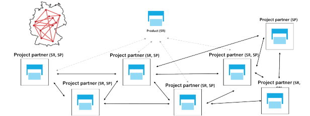 Figure 7-1: The demonstrator described in this document is part of an emerging networked Germany-wide I4.0 demonstrator
7 Summary and outlook
7.1 Bibliography
7.2 Appendix
7.2.1 Identifiers
7.2.2 Instances
7.2.3 Package Explorer and AASX files
7.2.4 Authors
results matching ""
No results matching ""
카탈로그
- 1 문서의 목적과 절차
- 2 모델링 대상
- 3 모델링 방법
- 4 P&P 스테이션의 선택된 구성 요소 모델링
- 5 AAS 모델링 개념
- 5.1 AAS의 기본 구조 및 선택된 중요 속성
- 5.2 요소 식별
- 5.3 Semantic assignment to model elements - the “semanticId”
- 5.4 Relationship between AAS, Asset and Asset Identification Submodel
- 5.5 Bill of material
- 5.6 The kind attribute - types/templates and instances
- 5.7 I4.0 Composite Component
- 5.8 Concept Descriptions and Data Specifications
- 5.9 Submodel templates
- 6 Metamodel references
- 7 Summary and outlook